If you’ve ever worked with inductors—whether designing power supplies, RF circuits, or electric vehicle drivetrains—you know how much a single component can make or break a project. Last month, I had a customer reach out to me frustrated: their new industrial inverter prototype was overheating, and their inductors were wasting 12% more energy than their simulations predicted. They’d followed all the standard rules for inductor design—picked the right core material, wound the correct number of turns, matched their switching frequency—but still, something was off. When I asked about their wire gauge and operating frequency, the lightbulb went off: they were running at 20 kHz with solid copper wire, and the skin effect was silently sabotaging their performance. Inductor

As an inductor supplier, I see this mistake all the time. Many engineers focus on core losses and winding resistance but overlook how the skin effect distorts current flow in wires—until it’s too late, and their devices are failing efficiency tests, overheating, or falling short of power ratings. Let’s break down what the skin effect actually is, how it impacts inductors, and what you can do to mitigate it to keep your designs running smoothly.
What Is the Skin Effect, Exactly?
At its core, the skin effect is a natural electromagnetic phenomenon that occurs when alternating current (AC) flows through a conductor. Unlike direct current (DC), which spreads evenly across the entire cross-section of a wire, AC generates a changing magnetic field around itself as it alternates. This magnetic field induces eddy currents in the conductor that oppose the main current. Near the center of the wire, these eddy currents work to cancel out the main current, while near the surface, they reinforce it. The end result? Most of the current flows only through the outer “skin” of the wire, leaving the interior effectively unused.
The depth of this skin layer—called the skin depth—depends on three key factors: the frequency of the AC current, the conductivity of the conductor, and the permeability of the material. For common copper wire, skin depth shrinks as frequency increases. At 50/60 Hz (standard mains power), skin depth is around 8.5 mm, so a typical 16-gauge wire (about 1.29 mm in diameter) has a cross-section almost entirely filled with current, making the skin effect negligible for low-frequency applications. But bump that up to 10 kHz, and skin depth drops to around 0.21 mm. At 100 kHz, it’s just 0.066 mm—tiny, and way smaller than most wire gauges used in inductors. That’s when the skin effect stops being a minor quirk and becomes a major design issue.
How the Skin Effect Hurts Inductor Performance
Now, let’s connect this to inductors specifically. Inductors store energy in their magnetic field, and their main job is to oppose changes in current—whether in a buck converter, a motor drive, or an RF matching network. But every inductor has parasitic losses, and the skin effect amplifies one of the biggest of these: winding AC resistance.
Here’s why that matters. Resistance in a wire is calculated by its length, conductivity, and cross-sectional area. For DC, that area is the full circle of the wire, so resistance is low. For AC, only the skin layer contributes to effective cross-sectional area. If you use a solid wire with a diameter larger than twice the skin depth at your operating frequency, most of the wire’s interior is just dead weight—copper that’s not carrying current, but still adding to the inductor’s weight, size, and (here’s the kicker) power loss.
Take that 20 kHz inverter customer I mentioned. They used a 2 mm diameter solid copper wire for their inductor winding. At 20 kHz, copper’s skin depth is 0.47 mm, so the effective current-carrying area is a hollow circle around the wire’s edge. The cross-sectional area of the wire is π*(1 mm)² = 3.14 mm², but the effective area is π*((1 mm)² – (0.53 mm)²) = ~2.25 mm². That’s a 28% drop in effective area, which means AC resistance is 28% higher than DC resistance. For their 100-turn inductor running at 5 A, that extra resistance added 0.7 W of loss—enough to cause the overheating they saw, and cut their inverter’s efficiency by 12% like they reported.
But the skin effect doesn’t just increase resistive loss. It also impacts the inductor’s inductance and self-resonant frequency (SRF)—two critical parameters for RF and high-frequency designs. Wait, inductance? How does the skin effect affect that? Let’s think: inductance is the ratio of magnetic flux to current, and the flux in a wire is tied to the current distribution. When current is concentrated near the surface, the magnetic field inside the wire (which contributes to the internal inductance of the winding) drops. That reduces the total inductance of the inductor. For a high-frequency RF inductor, a 5-10% drop in inductance can throw off an impedance matching network, leading to poor signal transfer or even signal reflection. And as inductance drops, SRF shifts too—SRF is the frequency where the inductor’s inductive reactance equals its capacitive reactance (from winding capacitance), so a lower inductance means SRF moves to a higher frequency. If your operating frequency is near the new SRF, the inductor stops behaving like an inductor entirely and acts like a capacitor, ruining circuit performance.
I’ve seen this play out in RF applications too. A few months back, a customer was designing a 100 MHz matching inductor for a wireless sensor. They used standard solid enameled wire, and their simulation predicted an inductance of 1.2 µH, perfect for their design. But when they built the prototype, the inductance measured 1.05 µH—12% lower—because at 100 MHz, copper skin depth is just 0.066 mm. The solid wire’s interior was almost unused, so the internal inductance dropped significantly. They ended up having to re-spin their circuit to accommodate the lower inductance, a delay that cost them weeks of production time.
Another hidden impact: copper weight and inductor size. To counteract the higher AC resistance from the skin effect, some engineers will just use a thicker solid wire to get the same effective cross-sectional area as a thinner wire at low frequency. But a thicker wire is bulkier, heavier, and more expensive. For a automotive inductor that needs to fit in a tight engine bay, or a power supply in a compact server rack, that extra size is a non-starter. And for high-volume production, the cost of that extra copper adds up fast—our inductor team has calculated that using the wrong wire due to skin effect can increase material costs by 30% or more without any performance gain.
Mitigating the Skin Effect: Solutions We Recommend
The good news is that the skin effect is predictable, so there are straightforward ways to mitigate its impact on inductor performance. As an inductor supplier, we work with customers every day to tailor solutions that fit their operating frequency, current rating, and size requirements. Here are the methods we see work best:
-
Litz Wire This is the gold standard for inductors operating above 1 kHz. Litz wire is made of many small, individually insulated strands twisted together. Each strand has a diameter smaller than the skin depth at the operating frequency, so each strand carries current across its full cross-section. The twisting also ensures that each strand is exposed to the same magnetic field, so no strand carries more current than another—eliminating the uneven current distribution that amplifies the skin effect. For our 20 kHz inverter customer, switching from 2 mm solid wire to 0.2 mm Litz wire (100 strands twisted together) cut their AC resistance back to near DC resistance, eliminating the overheating and efficiency loss. We’ve tested Litz wire designs that reduce AC losses by up to 90% compared to solid wire at 20 kHz, and even more at higher frequencies. The only tradeoff? Litz wire is slightly more expensive than solid wire, but the energy savings and performance gains almost always make it worth it for high-efficiency or high-frequency designs.
-
Parallel Solid Strands If Litz wire is out of budget for a low-cost design, using multiple thin solid wires in parallel is a close second. Instead of one thick wire, use two or three thin wires placed side by side, each with a diameter smaller than the skin depth. This gives you the same total cross-sectional area as a thick solid wire, but each strand operates at full efficiency. The key here is to make sure the strands are closely bundled and insulated, so their magnetic fields don’t interfere and cause a new issue called proximity effect (a related phenomenon where adjacent conductors interact to concentrate current even further). For low-frequency applications (up to 10 kHz), this is a simple, cost-effective fix.
-
Foam-Cored or Air-Core Windings For very high-frequency RF inductors (above 10 MHz), even Litz wire can have some residual skin effect loss. In these cases, using an air core or foam core (a non-magnetic, low-loss material) lets you use thicker solid wires or flat busbars, and the skin effect’s impact is less noticeable at the small number of turns typically used for RF inductors. We design many RF inductors for 5G applications this way, balancing size, loss, and inductance without overcomplicating the winding.
-
Proper Frequency Matching During Design This sounds obvious, but it’s worth repeating: always calculate skin depth before selecting wire for your inductor. A quick rule of thumb is that if your wire’s diameter is more than twice the skin depth, you’re losing efficiency to the skin effect. There are free online skin depth calculators, but if you work with our inductor team, we can run these calculations for you and recommend the right wire gauge or construction before you order.
Final Thoughts
At the end of the day, the skin effect isn’t a flaw—it’s a natural part of how AC and conductors interact. The mistake isn’t the skin effect itself, but overlooking it during design, which leads to avoidable performance issues, wasted materials, and delayed projects. As an inductor supplier, our job isn’t just to sell parts—it’s to help engineers build designs that work as intended, even when hidden phenomena like the skin effect are at play. Whether you’re working on a low-power home appliance, a high-voltage electric vehicle inverter, or a 5G base station, we can help you select the right inductor winding to minimize skin effect losses and get the performance you need.
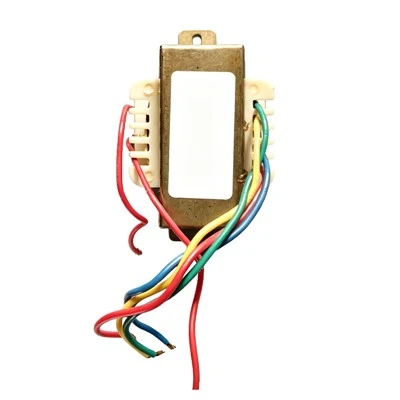
If you’re dealing with inductors that are overheating, underperforming, or not meeting your efficiency targets, or if you’re planning a new design and want to avoid skin effect pitfalls, reach out to us to discuss your requirements. We can provide sample inductors, run custom loss calculations, and help you find the optimal solution for your application. Let’s work together to make your next project a success.
Transformer References
- Snelling, E. C. Soft Ferrites: Properties and Applications. Butterworth-Heinemann, 1988.
- McNally, G. T. “Skin Effect in Conductors at Audio and Power Frequencies.” IEEE Transactions on Power Apparatus and Systems, vol. PAS-87, no. 3, 1968, pp. 597–604.
- Webster, J. G. Wiley Encyclopedia of Electrical and Electronics Engineering. John Wiley & Sons, 1999.
- El-Hawary, M. E. Electric Power Applications of Magnetic Components. CRC Press, 2001.
Wenzhou Mingyue Electric Co., Ltd.
As one of the most professional inductor manufacturers and suppliers in China, we have world-leading production equipment and strong manufacturing capabilities. Please feel free to wholesale durable inductor in stock here and get quotation from our factory. We also accept customized orders.
Address: No. 16, Zhongsan East Road, Donghuangyu Village, Liushi Town, Yueqing City, Wenzhou City, Zhejiang Province
E-mail: Hu17687922780@outlook.com
WebSite: https://www.cn-mingyue.com/
